Lower vehicle mounting position
The design prioritizes a low mounting surface to reduce the combined vertical space occupied by the platform and vehicle.
LOW-PROFILE · SIX DEGREES OF FREEDOM
YSL-MP-6DOF-7A-V1
Designed for full-vehicle simulation where indoor clearance is limited.
A layered motion mechanism balances vehicle mounting height with the six-axis motion envelope, providing a motion base for the customer's vehicle, cockpit and visual system.
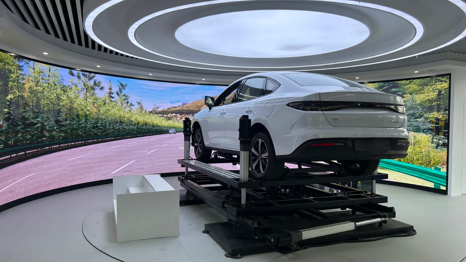
This product is a motion platform. The vehicle and large LED screens shown are not included in the standard supply.
Three translations · Three rotations
Two actuator groups, upper and lower
Drawing-specified load · Operating conditions confirmed per project
Reference working-platform dimensions
01 / DESIGNED AROUND YOUR SPACE
A vehicle already has its own height. Adding a motion platform requires further overhead clearance for heave and tilt. This structure originated in an upper-floor indoor vehicle simulation project with limited clearance.
The design prioritizes a low mounting surface to reduce the combined vertical space occupied by the platform and vehicle.
The lower mechanism handles surge, sway and yaw; the upper mechanism handles heave, pitch and roll, allowing the stroke of each group to be allocated separately.
Confirm the installation using payload height, center of gravity, motion poses and indoor clearance, together with floor load capacity and fixing conditions.
02 / SEVEN ACTUATORS. SIX DEGREES OF FREEDOM.
Seven electric actuators work together in two groups, with a defined mechanical role for each of the six degrees of freedom.
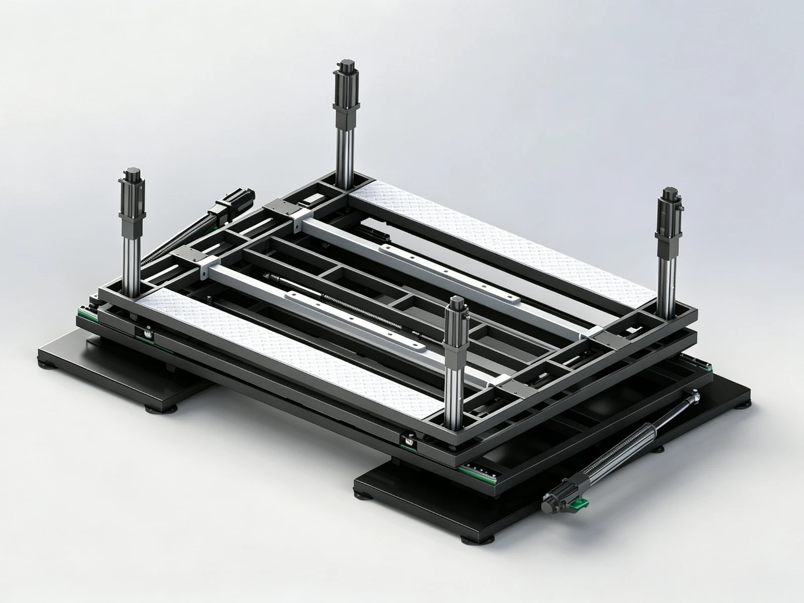
Synchronized and differential movement of four actuators changes the height and tilt of the load-bearing surface.
The lower mechanism moves the entire upper assembly to produce longitudinal and lateral travel and changes in heading.
For example, during pure longitudinal travel, the lower stage can move the entire upper assembly while the four upper actuators retain their lengths. This arrangement helps reduce stroke coupling between the two groups. Available travel within each group and in combined motion still depends on mechanism geometry and control limits.
03 / APPLICATION IN MOTION
Real footage shows a vehicle mounted on the motion platform and used with a large visual system.
Application scopeThe vehicle, large LED display system and site facilities are not included in this product's standard supply; project integration follows the agreed configuration.
04 / MOTION & INSTALLATION
Motion and dimensional values follow the current concept drawing; power and control deliverables follow this product configuration. Combined-motion limits, load conditions and mounting interfaces are confirmed in the project technical specification.
| Motion | Range | Speed |
|---|---|---|
| Heave | ±100 mm | 150 mm/s |
| Surge · longitudinal | ±250 mm | 150 mm/s |
| Sway · lateral | ±100 mm | 150 mm/s |
| Pitch | ±6.5° | 9°/s |
| Roll | ±10° | 9°/s |
| Yaw · heading | ±10° | 7°/s |
Individual-axis values do not imply that all maximum values can be reached simultaneously in any combined pose.
05 / PLATFORM SUPPLY & INTEGRATION
Define the supply around the platform structure, electric actuators and project motion requirements.
Control cabinet, drives and other hardware, together with payload-mounting adaptations, follow the order's technical equipment list.
The car, large LED screens and site facilities in the photos and video illustrate an application; they are not included as standard equipment with this product.
Motion control algorithms and an interface documentation package are provided to support platform control and integration with the customer's supervisory system.
Specific interface formats and integration scope are confirmed in the project technical specification.
Download product information, motion parameters and supply scope.
LET’S FIT THE PLATFORM TO YOUR PROJECT
Provide the following information to assess installation space, motion requirements and system integration.
This website presents selected multi-axis motion platform models and applications, rather than our full product range or all available configurations. If you cannot find a suitable model, contact us with your payload, motion range, installation space and application requirements. We can help recommend a suitable product or develop a custom solution for your project.
Specify how the total load is divided among the vehicle, occupants and mounting accessories, so the conditions applicable to the 1500 kg drawing value can be checked.
Advertising measurement
With your permission, we use Google Ads cookies to measure which ads lead to successful inquiries. You can reject measurement and still use the inquiry form. We do not send your form answers to Google or enable personalized advertising.
Cookie notice