Upgrade existing equipment
Assess retaining existing cockpits, seats, controls and displays while adding a motion platform. What can be retained depends on payload and mounting conditions.
STANDARD MOTION PLATFORM
YSL-MP-6DOF-6A-V1
Standard six-degree-of-freedom electric motion platform
For simulator manufacturers and system integrators: a motion base for flight, driving and marine simulation, also suitable for upgrading static simulators when payload, installation and software integration conditions are met.
This product is a motion platform. Cockpit, controls, displays and simulation software integration and supply must be confirmed separately.
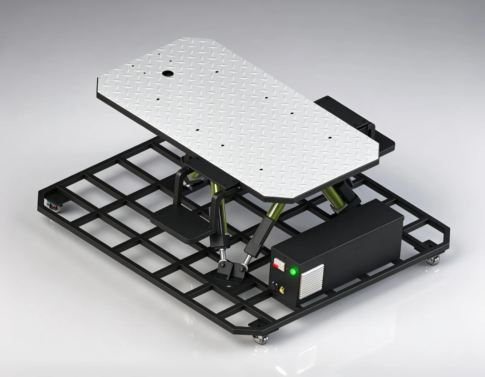
Three translations · Three rotations
Total load above the platform · centre of gravity assessed per project
Mounting deck dimensions
Equipment net weight
01 / FROM STATIC TO DYNAMIC
Customers with existing cockpits, displays and controls can check mechanical and software compatibility before defining a motion upgrade.
Assess retaining existing cockpits, seats, controls and displays while adding a motion platform. What can be retained depends on payload and mounting conditions.
Use an existing platform design and its parameters as the starting point, focusing more development work on simulation content, control systems and integration.
Plan static and motion versions of a simulator family or assess upgrades for existing customers. Shared structures and controls are confirmed per project.
Motion cues for flight attitude changes, take-off and landing.
Motion feedback for acceleration, braking, steering and road changes.
Heave, roll and pitch cues representing changing sea conditions.
These are application directions, not a promise of included simulation software or completed integration with every system. Results depend on simulation data, motion algorithms, available travel and commissioning.
02 / SIX DEGREES OF FREEDOM
Coordinated extension and retraction of six electric actuators changes deck position and attitude. Each direction is produced by the mechanism as a whole; one actuator does not correspond to just one degree of freedom.
Vertical translation
Forward / backward translation
Left / right translation
Forward / backward tilt
Side-to-side tilt
Heading rotation
Single-axis limits cannot necessarily be reached simultaneously in combined poses. Confirm the available envelope for the payload, centre of gravity and control limits.
03 / ACTUAL EQUIPMENT
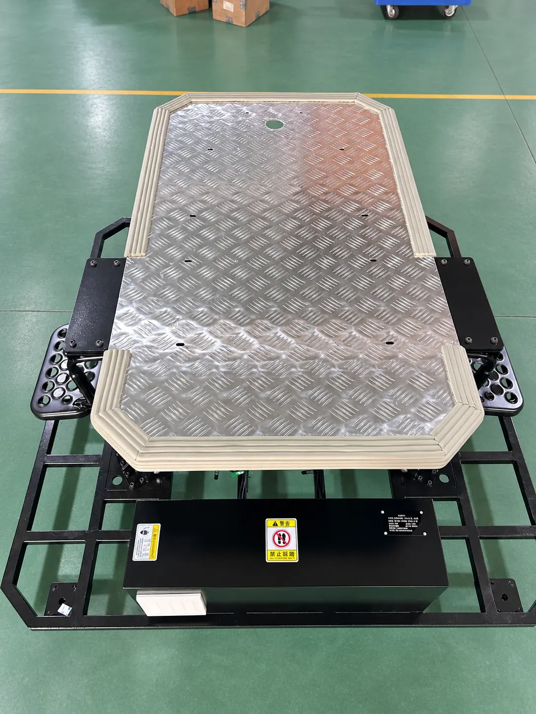
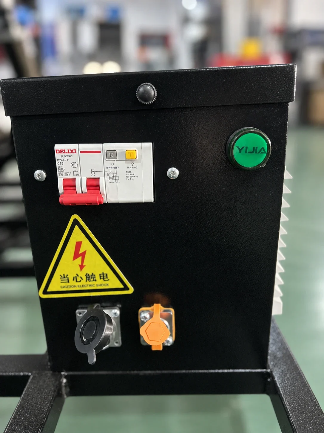
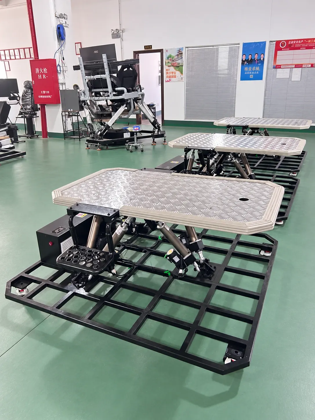
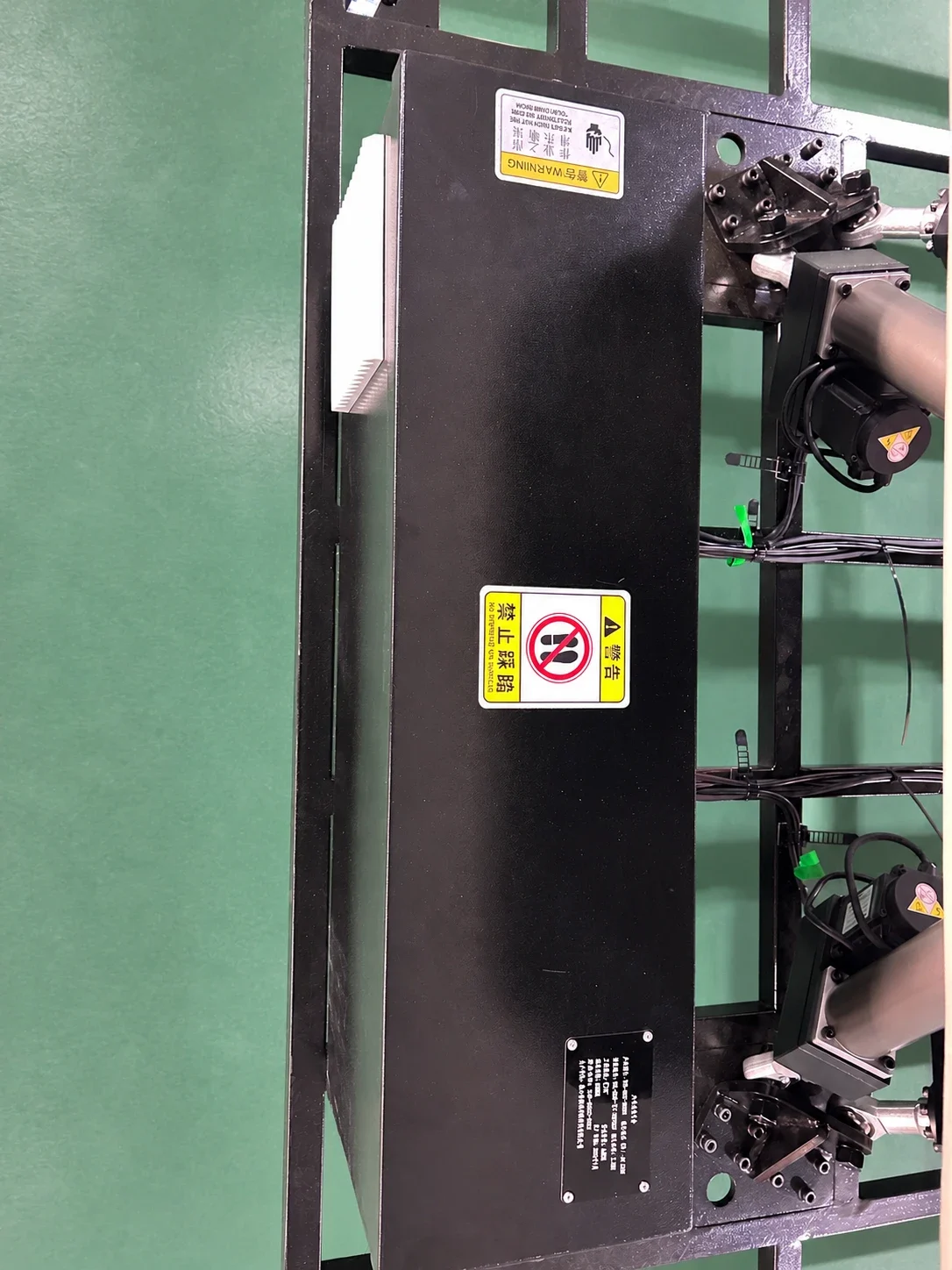
Close-up footage shows the structure; the multi-platform video demonstrates hand-controller operation with multiple axes and varying speeds. These demonstrations are not rated-load performance tests.
04 / SPECIFICATIONS
The platform load is 300 kg: the total weight placed on it. The amplitudes and speeds below are loaded maxima for each direction moving independently. Centre of gravity and off-centre loading are assessed against the customer’s load configuration.
| Motion | Range | Speed |
|---|---|---|
| Heave | ±70 mm | 250 mm/s |
| Longitudinal translation | ±100 mm | 250 mm/s |
| Lateral translation | ±100 mm | 250 mm/s |
| Pitch | ±12° | 25°/s |
| Roll | ±12° | 25°/s |
| Yaw | ±12° | 25°/s |
The total load includes the customer’s cockpit, seats, occupants, equipment and mounting accessories. Loaded maximum amplitudes and speeds in individual directions cannot necessarily be achieved simultaneously in combined motion. Load conditions and the combined workspace are confirmed for each project.
05 / INTEGRATION
We supply a complete six-DOF platform with an upper mounting deck. A plated deck or open frame can be supplied with provision for mounting holes. Upper mounting-hole details are provided after contact; cockpit dimensions, fixing points and load conditions define the mechanical interface.
A network cable connects the platform to the host. Customer software outputs real-time pose and time data. We provide motion-control algorithms, interface documentation and example calls. Protocol, data format, time definition, coordinate conventions and transmission rate are confirmed during integration.
Agree motion-cue objectives, limits and commissioning scope for the payload and application, then arrange system integration and acceptance.
Connect the host by network cable and integrate using the supplied algorithms, interface documentation and examples. Control prioritises real-time pose response; requested angles or displacement outside the available range are limited to executable values.
INSTALLATION & PROTECTION
The base can be secured with expansion anchors. For a small, low cockpit without significant centre-of-gravity offset, assessed load and installation conditions may allow support on levelling casters without anchors. Adjust their support feet fully to prevent base movement during operation. Confirm the fixing method against the customer’s load configuration.
An emergency-stop button on the control cabinet stops platform motion in an emergency.
Host angle and displacement commands are range-limited. Commands beyond the executable range are clamped, with priority given to real-time pose response within the available workspace.
On overload or a platform fault, an audible alarm sounds and motion stops.
On sudden power loss, the platform slowly descends to its lowest position.
06 / SUPPLY & DOCUMENTATION
Standard supply is one complete six-DOF platform, including control hardware, commissioning software and control-interface documentation. Mechanical mounting and software integration with the customer’s cockpit require coordination.
One complete six-DOF platform, including the mechanical structure, six electric actuators, controller, drives, control cabinet, cables, emergency stop and commissioning software.
Motion-control algorithms, interface documentation and example calls are supplied for customer integration using real-time pose and time data.
The customer provides cockpit mounting requirements. The mounting surface may be plated or an open frame with prepared fixing holes. The cockpit, displays and operator controls are not part of the platform’s standard supply.
Choose a plated deck or open frame, with fixing holes prepared to an agreed mounting drawing. Upper mounting-hole details are supplied after contact. Provide cockpit dimensions, fixing points, total weight above the platform and centre-of-gravity information to assess installation against the 300 kg load and customer load configuration.
Approximately 3 weeks; the starting conditions and delivery date are confirmed in the order.
Software, hardware and overall operation are checked before dispatch.
A user manual is supplied. Remote guidance for on-site installation and operating training are available when needed.
One-year hardware warranty. Standard new software features may be provided as free upgrades; confirm applicable terms with our sales team.
Remote troubleshooting assistance is available; overseas on-site service is not currently provided.
Download the product overview, motion specifications, supply scope and integration requirements.
TELL US ABOUT YOUR SIMULATOR
Tell us the application, payload dimensions and total weight, installation space and existing software interface so we can assess platform selection and integration.
This website presents selected multi-axis motion platform models and applications, rather than our full product range or all available configurations. If you cannot find a suitable model, contact us with your payload, motion range, installation space and application requirements. We can help recommend a suitable product or develop a custom solution for your project.
Advertising measurement
With your permission, we use Google Ads cookies to measure which ads lead to successful inquiries. You can reject measurement and still use the inquiry form. We do not send your form answers to Google or enable personalized advertising.
Cookie notice